We at Sun Ray Solar would like to extend our congratulations on your decision to purchase a solar water heating system and join the millions who use this cost-effective and reliable choice for hot water.
Established in 1978 as an innovative company, Sun Ray Solar has positioned itself to be the supplier of choice for those contractors and customers who demand the utmost reliability, performance and cost-effective solar heating systems. Sun Ray Solar offers a variety of solar water heating systems to meet your needs and requirements.
Please take the time to read this manual thoroughly before attempting to install the system. The Sun Ray Solar water heating system appropriate for your geographical and climatic area will provide you an efficient, reliable source of free hot water for years to come when installed according to this manual. Thank you for doing your part in energy conservation.
Systems description
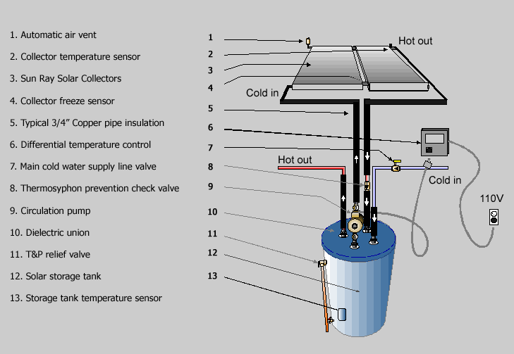
This manual describes the WH-1. Active, direct systems. (See System Diagram). The Model Sun Ray WH-1. is an active, direct system. This system uses potable water in the solar collector and it is open to the city pressures. The WH-1 is designed for installation in areas where the air temperature falling below 41° F does not occur more than 3 to 4 times annually and this low temperature does not exceed an 8-hour duration.
Major system components
Solar Collectors
 Sun Ray Solar collectors are the heart of the system. Their main function is to absorb solar radiation and transfer the heat collected to the fluid circulating through the system. In the northern hemisphere the ideal orientation of Sun Ray Solar collectors are directly south and tilted to the degree of your local latitude. The collectors are mounted in an area (roof or ground) with a full solar window.
Sun Ray Solar collectors are made of all copper or copper aluminum absorber plate with high performance absorber coating, isocyanurate back and side insulation board, and safety tempered glass cover. All enclosed in a corrosion resistant galvanized steel frame. The collector absorber plate can easily be repaired or replaced if needed.

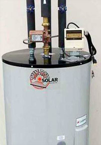
Solar water storage tank
The storage tank has a glass lining and an anode rod for maximum corrosion protection. Its internal manifold provides even distribution of heat and an injected foam insulation minimizes heat loss. The tank is available with or without an electrical element. (UL Listed, 5-year warranty)
Automatic controller
The controller is a differential temperature thermostat designed specifically to regulate a solar system operation. Its basic function is to monitor collector and storage temperatures and to automatically turn a small circulator ON or OFF at the appropriate temperature differentials. The controller can also provide additional functions, such as: system freeze protection (drain down / drain back or re-circulation), storage tank high temp. limit and positive OFF when the collector is below 80°F. (UL Listed. 5 year warranty)
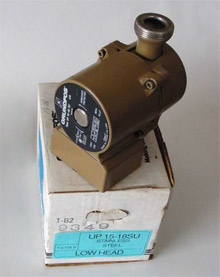
Low power circulation pump
 All vital components are fabricated from corrosion-resistant, high-grade stainless steel. This quiet, self-lubricating circulator is maintenance free, and requires very little energy to operate. (UL Listed. 18-month warranty)
Using the basic system diagram a variety of system types and sizes and can be installed.
Sizing the System
Storage tank: Select 15 to 20 gallon per person per day or 15 to 20 gallons per bedroom (min. 60 gallon tank)
Example: For four persons household or for four bedrooms home select 80-gallon storage tank
Solar collectors: Select one half to one sq/ft of solar panels per one gallon of storage
Example: 80-gallon tank will required 40 to 80 sq/ft of solar panels.
Installation
All plumbing, electrical and structural must be installed according to specific local codes.
Solar Collectors Tilt and Orientation
The ideal orientation of Sun Ray Solar collectors are directly south (northern hemisphere) and tilted to the degree of your local latitude, but any direction within 90° from south is acceptable if the total degree of tilt + the orientation angle from due south is less then 130°.
Example-1: The roof slope is 15° and is facing S.W. or 45° from south: therefore 15° +45° =60° or less then 130°.This is an acceptable orientation.
Example-2: The roof slope 45° and is facing W. or 90° from south: therefore 45° +90° =135° . This is more then 130° and is not in an acceptable orientation.
Minimum system installation standards
Install the system according to the diagram.
- The collectors should be installed as close in proximity as possible to the storage tank.
- The collectors should be mounted in an area with a full solar window.
- The collectors should be mounted with a minimum of 1 ½’ air gap above the roof sheeting.
- The collectors and pipe runs must sloped at least 4″ in 10 feet to allow a complete drainage.
- The collectors should be mounted in parallel positioning.
- The collectors mounting bolts should penetrate the roof rafters, or use a wood block under the sheeting.
- All roof penetrations should be sealed.
- Install collector array piping in a reverse-return configuration so that path lengths of collector supply and return are of approximately equal length.
- Install a freeze protection valve on the return line according to the diagram (optional).
- An air vent should be installed vertically on the highest point of the system.
- An air vent cup must remain loose for proper operation. The Air vent should be insulated
- The collector sensor should be mounted near the collector outlet.
- For best protection the freeze sensor should be mounted on the absorber in the center of the collector’s array.
- Sensor wires should not be exposed to direct sunlight.
- Wire nuts connecting the sensors should be filled with silicon to prevent any moisture from penetration the sensor.
- Use ¾” copper pipe for total runs of over 50 ft. Use ½” or ¾” for runs less then 50 ft.
- Use long 90’s and soft copper tubing as possible to minimize flow restrictions.
- All pipe runs should be insulated to an R-value of 2.6 or better. (7/8″ ID x 5/8″ wall) (Cold line 5′ from tank)
- All exterior pipe insulation should be protected from UV radiation and moisture. (Paint with exterior latex)
- Set the storage tank indoors close in proximity to 110V electrical outlets. Secure tank in event of an earthquake.
- Install a shut-off valve for the solar system so that the cold water supply is not interrupted.
- Install a T&P Relief Valve. The drain line should be discharged the to the outdoors no higher then 6″ above grade.
- Install the pump on the collectors feed line with the arrow pointing to the direction of flow. (To collectors)
- Install a thermosyphon prevention check valve on the collectors return line.
- Install the tank sensor on the threaded stud located behind the cover plate of the bottom portion of the tank.
- Mount the automatic controller on the tank or next to the 110V outlet.
- Install the controller according to the installation instructions provided with the controller.
- Follow the tank manufacturers instructions for high voltage connection of the electrical element and element timer.
- Attach the warning and instructions labels provided with the system.
Common Mounting Styles

Typical collector mounting on a tilted roof

Typical collector mounting on a flat roof

Typical wood collector mounting on a flat roof
Operation Instructions
Starting up for the first time:
At this point all electrical power to the system is off, the cold water supply valve is off, the collector isolation valves are off and the storage tank is empty. The air vent on top of the collectors is not installed so the collectors can be flushed.
(A) Fill the tank by turning on the main valve and allowing the air to flush out of the tank.
(B) Turn on the isolation valves to fill the collectors. (You can flush the impurities like loose solder; flax, joint compound ext. from the collectors threw the air vent thread connector).
(C) After the collectors have been flushed, install the air vent and pressurize the system, the automatic air vent will bleed remaining air out of the collectors if its plug is loosened. (The system must be free of air for the pump to circulate water).
(D) Once the system has been filled, follow the controller’s instructions for fine-tuning. Plug in the pump cord into the controller. Plug in the controller to the 110V outlet and set the controller switch to automatic operation.
(E) The system should begin functioning if the sun is shining. Within a few second the collectors return line will be very hot. Within a minute or two the return line should cool to about 10°F to 15°F higher than the feed line.
(F) Set the electrical element timer so it does not compete with the sun.
Normal Operation Description
When solar energy is available the automatically controlled pump circulates solar heated water from the collectors through the solar storage tank to reach the desired temperature (130° F to 180° F). The collector’s basic function is to capture the suns energy and to transfer the heat collected to the fluid circulating throughout the system.
The controllers basic function is to monitor collector and storage temperatures and to automatically turn the pump ON or OFF at the appropriate temperature.
The solar storage tanks basic function is to store the energy collected. The tank is equipped with an electrical element and becomes a water heater as a backup. A timer can be added to control the electrical element so it cannot compete with the sun’s energy.
System Maintenance
Sun Ray Solar water heating systems require relatively little attention. But, as with any mechanical system, some basic maintenance is essential to keep the system functioning smoothly. The maintenance requirements of Sun Ray Solar water heating system are similar to those of conventional water heaters. The collectors, piping and storage tank should be checked for leaks, the system should be flushed periodically to remove tank and collected impurities (scaling in hard water areas). The systems should be checked at least twice per year for a proper operation of the pump, controller and sensors. The collector’s glass can be rinsed periodically to remove dust collected in order to improve collector efficiency.
Freeze protection
When the water in the collector reaches a temperature near freezing, the system’s freeze protection mechanisms will protect it as followed:
(A) The controller turns the pump on and off periodically to warm the collector with water from the storage tank.
(B) A flush-type freeze protection valve can be installed near the collectors opens to let warm water flow through the collector.
(C) For a longer freeze duration or if a power failure and freeze condition occurs at the same time. the collector must be manually drained (see Collector isolation and drainage above).
Note: Sun Ray Solar is the manufacture of the solar collectors for this system and offers this system major component as a package. Each major component comes with its own manufacturers warranty and its installation instructions.
The system installation is warranted by the contractor or the individual who installs the system.
